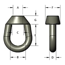
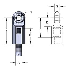
Industrial Threaded Products
Beam Clamps Center Load Clamps Fig. 229
(631)665-9300

product

Malleable Beam Clamp with Extension Piece – Fig. 229

For more product information please call (631) 665-9300
Diagram Notes

Clamp (Fig. 218) with Extension piece (Fig. 157)

Material

Malleable iron.

Finish

Plain or electro-galvanized.

Service

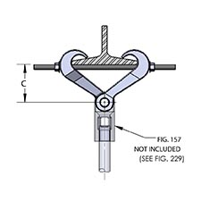
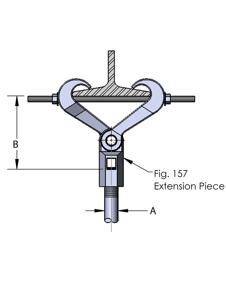
Designed for the suspension of a hanger rod from the center of an I-beam. The clamp accommodates flange widths of 2 3/8" - 7". Flange thickness not to exceed .60 inches. Normally used in conjunction with figure 157 extension piece. Figure 157 provides 1" of vertical adjustment.

Approvals

When used with FIG. 157 Extension Piece, complies with Federal Specification WW-H-171-E (Type# 30), A-A-1192 A (Type# 30) and Manufacturers' Standardization Society MSS SP-58 and SP-69 (Type# 30).

Ordering

Specify figure number and finish.

Notes

For complete assembly with extension piece see FIG. 229.

  • Size A
    3/8-16 
    1/2-13 
    5/8-11
    3/4-10 
    7/8-9
  • Bolt Dia
    7/16 
    7/16 
    7/16
    7/16 
    7/16
  • Wgt Each (lbs)
    2.42 
    2.63 
    2.67
    2.87 
    3.01
  • Max Rec Load (lbs)
    610 
    1130 
    1365
    1365 
    1365
B Rod Take Out for Width of Beam Flange
  • 2 3/8
    4 3/4 
    4 7/8 
    4 15/16
    5 3/16 
    5 1/4
  • 3
    4 11/16 
    4 13/16 
    4 7/8
    5 1/8 
    5 3/16
  • 4
    4 9/16 
    4 11/16 
    4 3/4

    5 1/16
  • 5
    4 3/16 
    4 5/16 
    4 3/8
    4 5/8 
    4 11/16
  • 6
    3 13/16 
    3 15/16 
    4
    4 1/4 
    4 5/16
  • 7
    3 1/8 
    3 1/4 
    3 5/16
    3 9/16 
    3 5/8
Items Commonly Used With