Industrial Threaded Products
Seismic Attachments Fig. 1001
(631)665-9300

Sway Brace Attachment

Sway Brace Attachment – Fig. 1001

For more product information please call (631) 665-9300
Diagram Notes

There are currently no diagram notes for this product.

Material

Carbon Steel, also available in 304 and 316 stainless steel

Finish

Plain or Electro-Galvanized.

Service

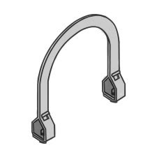
For bracing pipe against sway and seismic disturbance.

Approvals

Underwriters Laboratories Listed in the USA (UL) and Canada (cUL). Approved by Factory Mutual Engineering (FM). Approved by the State of California Office of Statewide Health Planning and Development (OSHPD). 

Ordering

Indicate pipe size to be braced, followed by pipe size used for bracing, figure number, and finish.

Notes

The cross reference number for this product is Fig 015

Click Here for cross reference page for this product.
distributedistributedistributedomestic
  • Pipe Size
    in (mm)
    1 (25)
    1-1/4 (32)
    1-1/2 (40)
    2 (50)
    2-1/2 (65)
    3 (80)
    4 (100)
    6 (150)
    8 (200)
Approximate Weight/100
1” Brace Pipe
1-1/4” Brace Pipe
  • Lbs
    100.0
    100.0
    100.0
    108.0
    138.6
    147.2
    160.9
    190.0
    217.4
  • (Kg)
    45.3
    45.3
    45.3
    49.0
    62.8
    66.7
    73.0
    86.2
    98.6
  • Lbs
    118.0
    114.0
    115.0
    121.0
    160.4
    168.7
    182.4
    211.4
    238.8
  • (Kg)
    53.5
    51.7
    52.1
    54.9
    72.7
    76.5
    82.7
    95.9
    108.3
Max Horizontal Design Load (FM) *
30-44 degrees
45-59 degrees
60-74 degrees
75-90 degrees
  • Lbs
    1800
    1230
    1230
    1230
    800
    850
    850
    510
    510
  • (kN)
    8.00
    5.47
    54.7
    5.47
    3.56
    3.78
    3.78
    2.27
    2.27
  • Lbs
    2550
    1740
    1740
    1740
    1130
    1200
    1200
    730
    730
  • (kN)
    11.34
    7.74
    7.74
    7.74
    5.02
    5.34
    5.34
    3.25
    3.25
  • Lbs
    3120
    2140
    2140
    2140
    1380
    1470
    1470
    890
    890
  • (kN)
    13.88
    9.52
    9.52
    9.52
    6.14
    6.54
    6.54
    3.96
    3.96
  • Lbs
    3490
    2380
    2380
    2380
    1540
    1640
    1640
    990
    990
  • (kN)
    25.52
    10.58
    10.58
    10.58
    6.85
    7.29
    7.29
    4.40
    4.40
* Max Horizontal Design Load (FM) Notes

-For Sch 7, Sch 10, & Sch 40 Pipe

- FM Approved when used with 1 or 1-1/4 inch NPS Schedule 40 GB/T 3091, EN 10255H, or JIS G3451 steel pipe as the brace member.

- Load rating for LW above refers to FM Approved Lightwall Pipe commonly referred to as “Schedule 7”. These ratings may also be applied with EN 10220 and GB/T 8163 steel pipe.

- Load rating for “Schedule 10” above may be applied to GB/T 3092, EN 10255M, and H, or JIS G3454, FM Approved Thinwall, or “Schedule 40” steel pipes.

  • Pipe Size
    in (mm)
    1 (25)
    1-1/4 (32)
    1-1/2 (40)
    2 (50)
    2-1/2 (65)
    3 (80)
    4 (100)
    6 (150)
    8 (200)
Max Horizontal Design Load (UL) – Lbs
Schedule 7
Schedule 10
Schedule 40
  • 1”
    -
    1000
    1000
    1000
    1600
    1600
    1600
    1600
    1600
  • 1-1/4
    -
    1000
    1000
    1000
    1600
    1600
    1600
    1600
    1600
  • 1”
    1000
    1000
    1500
    2015
    2015
    2015
    2015
    2015
    2015
  • 1-1/4
    1000
    1000
    1500
    2015
    2015
    2015
    2015
    2015
    2015
  • 1”
    1000
    1000
    1500
    2015
    2015
    2015
    2015
    2015
    2015
  • 1-1/4
    1000
    1000
    1500
    2015
    2015
    2015
    2015
    2015
    2015