Industrial Threaded Products
Seismic Attachments Fig 040
(631)665-9300

product

Supporting Pipe Attachment – Fig 040

For more product information please call (631) 665-9300
Diagram Notes

There are currently no diagram notes for this product.

Material

Carbon Steel, also avaialable in 304 and 316 stainless steel

Finish

Plain, Electro-Plated

Service

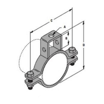
For bracing pipe against sway and seismic disturbance.

Approvals

Approved by the State of California Office of Statewide Health Planning and Development (OSHPD).

Ordering

Specify pipe size and finish.

Notes

The cross reference number for this product is Fig 4B

Click Here for cross reference page for this product
  • Pipe Size
    Sch 10 & 40
    in (mm)
    2 (50)
    2-1/2 (65)
    3 (80)
    3-1/2 (90) *
    4 (100)
    5 (125)
    6 (150)
    8 (200)
  • Hanger
    Rod Size
    in (mm)
    3/8 (10)
    1/2 (12)
    1/2 (12)
    1/2 (12)
    5/8 (16)
    5/8 (16)
    3/4 (20)
    3/4 (20)
Rec Max Hanger Load
Max Design Sway Brace Load
Weight
each
  • Lbs
    730
    850
    1000
    1000
    1000
    1600
    1600
    2015
  • kN
    3.25
    3.78
    4.45
    4.45
    4.45
    7,12
    7,12
    8.96
  • Lbs
    1000
    1000
    1000
    1000
    1000
    1600
    1600
    2015
  • kN
    4.45
    4.45
    4.45
    4.45
    4.45
    7.12
    7.12
    8.96
  • Lbs
    2.40
    2.58
    2.80
    2.94
    3.28
    4.95
    6.93
    9.97
  • kg
    1.09
    1.17
    1.27
    1.33
    1.49
    2.25
    3.14
    4.52

Chart Notes

- UL Maximum Design Load

* Sch 40 only

  • Pipe Size *
    in (mm)
    2 (50)
    2-1/2 (65)
    3 (80)
    3-1/2 (90)
    4 (100)
    5 (125)
    6 (150)
    8 (200)
Lateral
30 – 44 degrees
45 – 59 degrees
60 – 74 degrees
75 – 90 degrees
  • Lbs
    1070
    960
    960
    960
    960
    960
    1000
    1350
  • kN
    4.75
    4.27
    4.27
    4.27
    4.27
    4.27
    4.44
    6.00
  • Lbs
    1520
    1360
    1360
    1360
    1360
    1360
    1420
    1900
  • kN
    6.76
    6.04
    6.04
    6.04
    6.04
    6.04
    6.31
    8.45
  • Lbs
    1860
    1670
    1670
    1670
    1670
    1670
    1740
    2330
  • kN
    8.27
    7.42
    7.42
    7.42
    7.42
    7.42
    7.73
    10.36
  • Lbs
    2080
    1860
    1860
    1860
    1860
    1860
    1940
    2600
  • kN
    9.25
    8.27
    8.27
    8.27
    8.27
    8.27
    8.62
    11.56

Chart Notes

- FM Maximum Design Load

* Pipe size Sch 10, Sch 40, & Flow Pipe

  • Pipe Size *
    in (mm)
    2 (50)
    2-1/2 (65)
    3 (80)
    3-1/2 (90)
    4 (100)
    5 (125)
    6 (150)
    8 (200)
Longitudinal
30 – 44 degrees
45 – 59 degrees
60 – 74 degrees
75 – 90 degrees
  • Lbs
    1260
    1000
    1000
    1000
    1110
    1110
    1280
    1160
  • kN
    5.60
    4.44
    4.44
    4.44
    4.93
    4.93
    5.69
    5.15
  • Lbs
    1440
    1420
    1420
    1420
    1490
    1490
    1810
    1650
  • kN
    6.40
    6.31
    6.31
    6.31
    6.62
    6.62
    8.05
    7.33
  • Lbs
    1740
    1740
    1740
    1740
    1800
    1800
    2210
    2020
  • kN
    7.73
    7.73
    7.73
    7.73
    8.00
    8.00
    9.83
    8.98
  • Lbs
    1940
    1940
    1940
    1940
    1920
    1920
    2470
    2250
  • kN
    8.62
    8.62
    8.62
    8.62
    8.54
    8.54
    10.98
    10.00

Chart Notes

- FM Maximum Design Load

* Pipe size Sch 10, Sch 40, & Flow Pipe