Industrial Threaded Products
Strut Fig. 7241
(631)665-9300

product

2-7/16” x 1-5/8” 12 Gauge Back-to-Back Strut Slotted – Fig. 7241

For more product information please call (631) 665-9300
Diagram Notes

There are currently no diagram notes for this product.

Finish

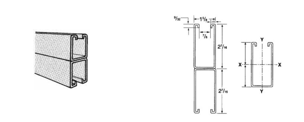
Plain, pre-galvanized, green painted

Standard Length

10’ or 20’

Weight Per Foot (Lbs)

5.04

Notes

304 and 316 stainless, PVC coated and hot-dipped galvanized are available.
Follow step 3 in the “Notes for the Below Chart” section for the specifications for this product.

53df7dd16d41053779165789_domestic_icons_03.jpg
  • ITP
    Figure Number
    7230
    7240
  • Wgt/Ft
    Lbs
    2.54
    5.08
  • Area of Section
    Sq. In.
    0.741
    1.142
X-X Axis
  • I in^4
    0.509
    2.721
  • S in^3
    0.378
    1.1410
  • r in
    0.844
    1.381
Y-Y Axis
  • I in^4
    0.331
    0.663
  • S in^3
    0.408
    0.815
  • r in
    0.681
    0.681

I = Moment of Inertia
S = Section Modulus
r = Radius of Gyration

Notes for the Below Chart:

* Not recommended – KL/r exceeds 200
**For These Loads, the uniform beam capacity is lower than the L/240 or L360 beam capacity and is therefore the governing restraint.
*** Load limited by spot-weld shear.

1. The beam capacities shown above include the weight of the strut beam. The beam weight must be subtracted from these capacities to arrive at the net beam capacity.

2. Allowable beam loads are based on a uniform loaded, simply supported beam. For capacities of a beam loaded at mid-span at a single point, multiply the beam capacity by 50% and deflection by 80%.

3. The below chart shows beam capacities for strut without holes. For strut with holes, multiply the following: 7/8” diameter Knockout by 82%, Round Hole 3/4” by 85% and Round Hole 9/16” by 88%, Slotted 9/16” x 1-1/8” by 88%, 13/32” x 3” by 90%

  • Span or Column (in)
    12
    12
    18
    18
    24
    24
    30
    30
    36
    36
    42
    42
    48
    48
    60
    60
    72
    72
    84
    84
    96
    96
    108
    108
    120
    120
    180
    180
    240
    240
  • ITP
    Figure
    Number
    7230
    7240
    7230
    7240
    7230
    7240
    7230
    7240
    7230
    7240
    7230
    7240
    7230
    7240
    7230
    7240
    7230
    7240
    7230
    7240
    7230
    7240
    7230
    7240
    7230
    7240
    7230
    7240
    7230
    7240
  • Max Load of
    Column Loaded
    @ C.G. (lbs)
    9,774
    20,586
    8,861
    19,931
    7,744
    19,144
    6,524
    18,304
    5,275
    17,474
    4,284
    16,693
    3,629
    15,981
    2,824
    14,790
    2,346
    13,881
    2,021
    12,054
    1,584
    7,434
    1,585
    4,971
    1,422
    6,022
    *
    *
    *
    *
Static Beam Load
  • Allowable Uniform Load
    @25,000 PSI (lbs)
    6,305
    3,880 ***
    4,203
    3,880 ***
    3,125
    3,880 ***
    2,522
    3,880 ***
    2,102
    3,880 ***
    1,801
    3,880 ***
    1,576
    3,880 ***
    1,261
    3,803
    1,051
    3,169
    901
    2,716
    788
    2,377
    701
    2,113
    630
    1,901
    420
    1,268
    315
    951
  • Deflection
    @ 25,000 PSI (in)
    0.009
    0.005
    0.0021
    0.012
    0.038
    0.021
    0.059
    0.033
    0.085
    0.048
    0.116
    0.065
    0.151
    0.085
    0.236
    0.133
    0.340
    0.192
    0.463
    0.261
    0.605
    0.341
    0.765
    0.431
    0.945
    0.532
    2.126
    1.199
    3.780
    2.131
  • Uniform Load
    @ L/240 (lbs)
    **
    **
    **
    **
    **
    **
    **
    **
    **
    **
    **
    **
    **
    **
    **
    **
    927
    **
    681
    **
    521
    **
    412
    **
    334
    1,784
    148
    793
    83
    446
  • Uniform Load
    @ L/360 (lbs)
    **
    **
    **
    **
    **
    **
    **
    **
    **
    **
    **
    **
    1,390
    **
    890
    **
    618
    **
    454
    2,427
    347
    1,858
    275
    1,468
    222
    1,189
    99
    529
    56
    297